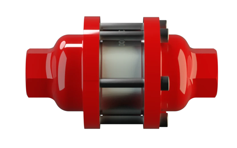
DA-G
In-Line Detonation Flame Arrester for stable detonations and deflagrations in a straight through design, bidirectional
Features
Modular Design
Directional
Fastest Disassembly and Assembly
Versatile Application Options
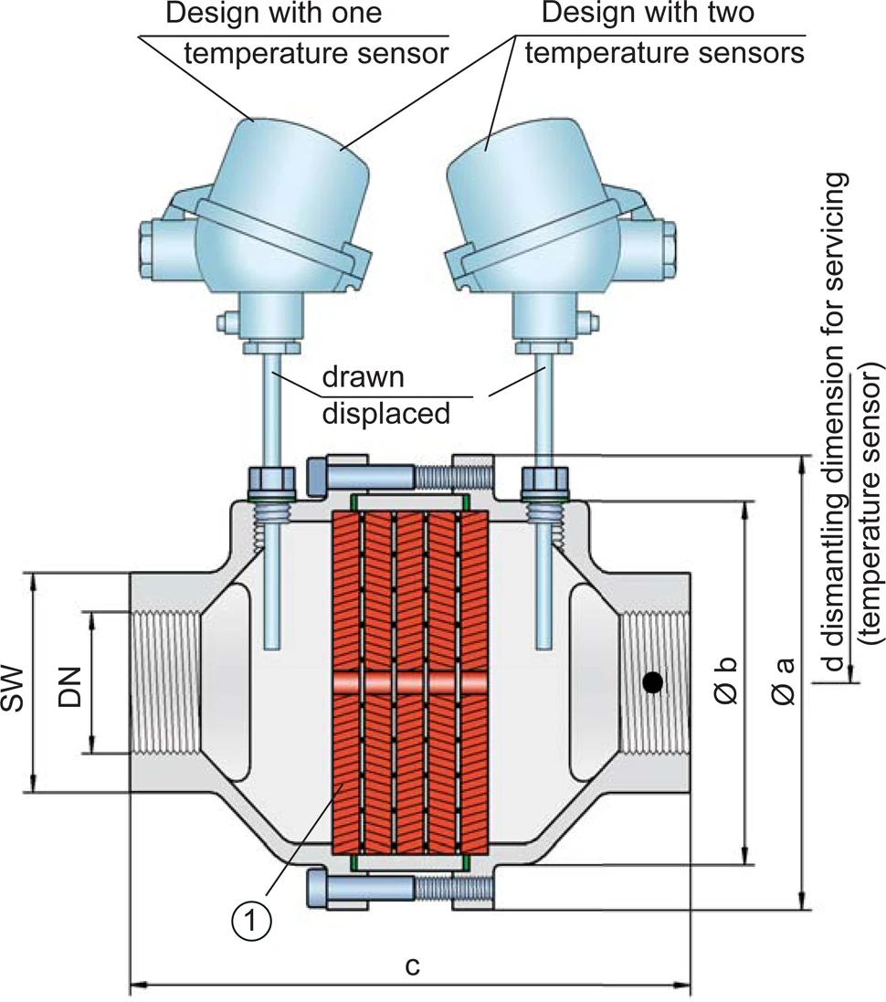
Temperature Sensors Possible
Spare Parts
For Industrial Use in Gas Analysis Lines

Main Component – PROTEGO® Flame Arrester Unit

Many Individual Certifications
Dimensions
To select the nominal size Diamètre nominal The nominal size is an alphanumeric designation of size for components in a piping system, used for reference purposes, comprising the letters DN followed by a dimensionless integer that is indirectly related to the physical size of the bore or outside diameter of the connections, expessed in millimeters. (DN), please use the flow capacity charts on the following pages
| DN | G ½" | G ¾" | G 1" | G 1¼" | G 1½" | G 2" |
| a | 80 / 3.15 | 80 / 3.15 | 100 / 3.94 | 100 / 3.94 | 155 / 6.10 | 155 / 6.10 |
| b | 55 / 2.17 | 55 / 2.17 | 76 / 2.99 | 76 / 2.99 | 124 / 4.88 | 124 / 4.88 |
| c (IIA) | 112 / 4.41 | 112 / 4.41 | 122 / 4.80 | 122 / 4.80 | 205 / 8.07 | 205 / 8.07 |
| c (IIB3 and IIC) | 135 / 5.31 | 135 / 5.31 | 145 / 5.71 | 145 / 5.71 | 205 / 8.07 | 205 / 8.07 |
| d | — | — | — | — | 400 / 15.75 | 400 / 15.75 |
| SW | 32 / 1.26 | 32 / 1.26 | 50 / 1.97 | 50 / 1.97 | 75 / 2.95 | 75 / 2.95 |
Dimensions in mm / inches, SW= width across flats
Selection of explosion group
| MESG | Expl. Gr. (IEC / CEN) | Gas Group (NEC) |
| > 0,90 mm | IIA | D |
| ≥ 0,65 mm | IIB3 | C |
| < 0,50 mm | IIC | B |
Special approvals upon request
Selection of max. operating pressure
| Expl. Gr. | DN | G ½" | G ¾" | G 1" | G 1¼" | G 1½" | G 2'' |
| IIA | Pmax | 1,2 / 17.4 | 1,2 / 17.4 | 1,1 / 15.9 | 1,1 / 15.9 | 1,1 / 15.9 | 1,1 / 15.9 |
| IIB3 | Pmax | 1,1 / 15.9 | 1,1 / 15.9 | 1,1 / 15.9 | 1,1 / 15.9 | 1,4 / 20.3 | 1,4 / 20.3 |
| IIC | Pmax | 1,1 / 15.9 | 1,1 / 15.9 | 1,1 / 15.9 | 1,1 / 15.9 | 1,6 / 23.2 | 1,6 / 23.2 |
Pmax = maximum allowable operating pressure in bar / psi absolute, higher operating pressure upon request
Specification of max. operating temperature
| ≤ 60°C / 140°F | Tmaximum allowable operating temperature in °C |
| - | Designation |
higher operating temperatures upon request
Material selection for housing
| Design | B | C |
| Housing | Stainless Steel | Hastelloy |
| Gasket | PTFE | PTFE |
| FLAMEFILTER®* | Stainless Steel | Hastelloy |
* the FLAMEFILTER® are also available in the materials Tantalum, Inconel, Copper, etc. when the listed housing and cage materials are used.
Special materials upon request
Type of connection
| Pipe thread DIN ISO 228-1 | DIN |
other types of thread upon request
Flow Capacity Chart
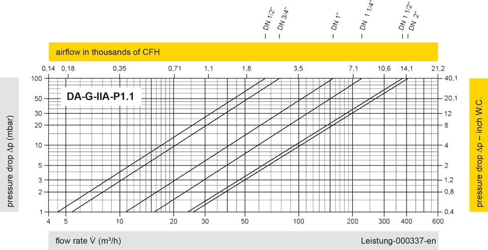
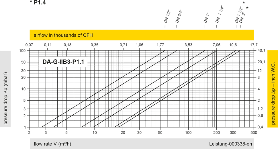
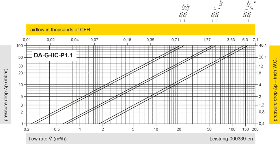
The flow capacity charts have been determined with a calibrated and TÜV certified flow capacity test rig. Volume flow V in (m³/h) and CFH refer to the standard reference conditions of air ISO 6358 (20°C, 1bar). For conversion to other densities and temperatures refer to Sec. 1: “Technical Fundamentals”.


Si vous avez des questions, des commentaires ou des suggestions, notre équipe d'experts se fera un plaisir de vous aider.
