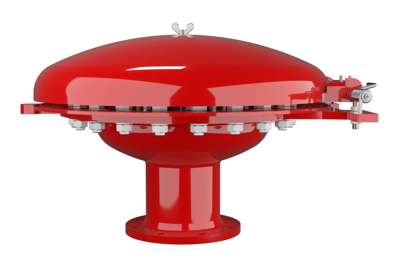
EB
Deflagration Flame Arrester, endurance burning proof, End-of-Line
Features
Comprehensive Weather Protection
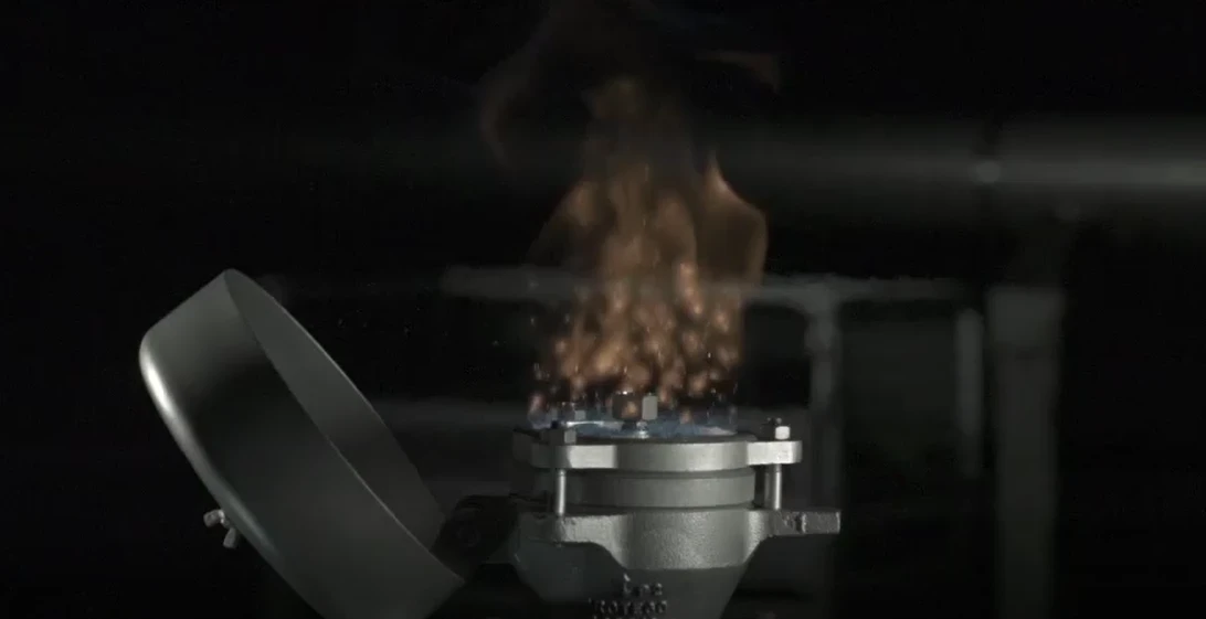
Visible Fire Indication by Tilting Weather Hood
Safety Against Deflagrations and Hydrocarbon Fires
Chemically Resistant
Modular Design
Easy Maintenance
Spare Parts
Protection Against Atmospheric Deflagration and Endurance Burning
Main Component – PROTEGO® Flame Arrester Unit

For Explosion Group IIB and IIA
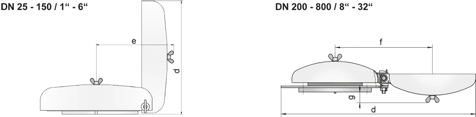
Dimensions DN 25 - 150 for EB-IIA and IIB
To select the nominal size Diamètre nominal The nominal size is an alphanumeric designation of size for components in a piping system, used for reference purposes, comprising the letters DN followed by a dimensionless integer that is indirectly related to the physical size of the bore or outside diameter of the connections, expessed in millimeters. (DN), please use the flow capacity chart on the following page
| DN | 25 / 1" | 32 / 1¼“ | 40 / 1½“ | 50 / 2“ | 65 / 2½“ | 80 / 3“ | 100 / 4" | 125 / 5" | 150 / 6" |
| a | 218 / 8.58 | 218 / 8.58 | 218 / 8.58 | 218 / 8.58 | 218 / 8.58 | 353 / 13.90 | 353 / 13.90 | 353 / 13.90 | 353 / 13.90 |
| b | 113 / 4.45 | 113 / 4.45 | 113 / 4.45 | 113 / 4.45 | 113 / 4.45 | 113 / 4.45 | 113 / 4.45 | 113 / 4.45 | 113 / 4.45 |
| c | 232 / 9.13 | 232 / 9.13 | 232 / 9.13 | 232 / 9.13 | 232 / 9.13 | 306 / 12.05 | 306 / 12.05 | 306 / 12.05 | 306 / 12.05 |
| d | 222 / 8.74 | 222 / 8.74 | 222 / 8.74 | 222 / 8.74 | 222 / 8.74 | 355 / 13.98 | 355 / 13.98 | 355 / 13.98 | 355 / 13.98 |
| e | 217 / 8.54 | 217 / 8.54 | 217 / 8.54 | 217 / 8.54 | 217 / 8.54 | 322 / 12.68 | 322 / 12.68 | 322 / 12.68 | 322 / 12.68 |
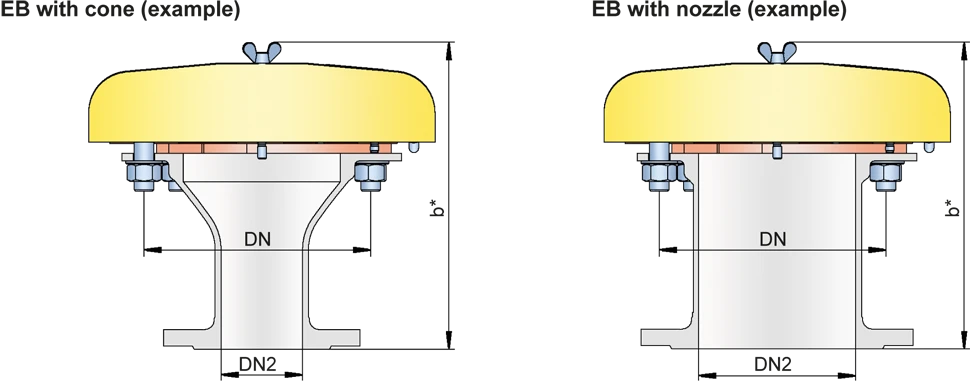
| EB-IIA and IIB with cone / nozzle** | |||||||||
| DN | 50 / 2" | 80 / 3" | 100 / 4" | 150 / 6" | |||||
| DN2 | ≤50 / 2“ | ≤80 / 3“ | ≤100 / 4 | ≤150 / 6“ | |||||
| b* | 238 / 9.37 | 263 / 10.35 | 383 / 15.08 | 313 / 12.32 | |||||
| Dimensions DN 200 - 800 / 8“ - 32“ for EB-IIA | |||||||||
| DN | 200 / 8" | 300 / 12" | 400 / 16" | 500 / 20" | 600 / 24" | 800 / 32“ | |||
| a | 405 / 15.94 | 555 / 21.85 | 705 / 27.75 | 855 / 33.66 | 1005 / 39.57 | 1210 / 47.64 | |||
| b | 177 / 6.97 | 206 / 8.11 | 235 / 9.25 | 265 / 10.43 | 294 / 11.57 | 330 / 12.99 | |||
| c | 496 / 19.53 | 650 / 25.59 | 802 / 31.57 | 987 / 38.86 | 1137 / 44.76 | 1336 / 52.60 | |||
| d | 900 / 35.43 | 1200 / 47.24 | 1500 / 59.06 | 1820 / 71.65 | 2120 / 83.46 | 2525 / 99.41 | |||
| f | 450 / 17.72 | 600 / 23.62 | 750 / 29.53 | 920 / 36.22 | 1070 / 42.13 | 1270 / 50.00 | |||
| g | 51 / 2.01 | 80 / 3.15 | 109 / 4.29 | 138 / 5.43 | 167 / 6.57 | 204 / 8.03 | |||
| EB-IIA with cone / nozzle** | |||||||||
| DN | 200 / 8" | 300 / 12" | 400 / 16" | 500 / 20" | 600 / 24" | 800 / 32" | |||
| DN2 | ≤200 / 8“ | ≤300 / 12“ | ≤400 / 16“ | ≤500 / 20“ | ≤600 / 24“ | ≤800 / 32“ | |||
| b* | 401 / 15.94 | 456 / 17.95 | 535 / 21.06 | 614 / 24.17 | 693 / 27.28 | 830 / 32.68 |
Dimensions in mm / inches
** combinations (DN/DN2) please use the table on the following page
Combination (DN/DN2) for EB with cone
Flow capacity charts for EB-DN/DN2-IIA/IIB with cone upon request
| DN | 50 / 2“ | 80 / 3“ | 100 / 4“ | 150 / 6“ | 200 / 8“ | 300 / 12“ | 400 / 16“ | 500 / 20“ | 600 / 24“ | 800 / 32“ |
| DN2 | ||||||||||
| 20 / ¾“ | IIA / IIB | IIA / IIB | IIA / IIB | IIA / IIB | ||||||
| 25 / 1“ | IIA / IIB | IIA / IIB | IIA / IIB | IIA / IIB | ||||||
| 32 / 1¼" | IIA / IIB | IIA / IIB | IIA / IIB | IIA / IIB | ||||||
| 40 / 1½" | IIA / IIB | IIA / IIB | IIA / IIB | IIA / IIB | ||||||
| 50 / 2“ | IIA / IIB | IIA / IIB | IIA / IIB | IIA / IIB | IIA | |||||
| 65 / 2½“ | IIA / IIB | IIA / IIB | IIA / IIB | |||||||
| 80 / 3“ | IIA / IIB | IIA / IIB | IIA / IIB | IIA | IIA | |||||
| 100 / 4“ | IIA / IIB | IIA / IIB | IIA | IIA | ||||||
| 125 / 5“ | IIA / IIB | IIA | ||||||||
| 150 / 6“ | IIA / IIB | IIA | IIA | IIA | ||||||
| 200 / 8“ | IIA | IIA | IIA | IIA | IIA | |||||
| 250 / 10“ | IIA | IIA | IIA | |||||||
| 300 / 12“ | IIA | IIA | IIA | |||||||
| 350 / 14“ | IIA | IIA | ||||||||
| 400 / 16“ | IIA | IIA | IIA | |||||||
| 450 / 18“ | IIA | IIA | IIA | |||||||
| 500 / 20“ | IIA | IIA | ||||||||
| 600 / 24“ | IIA | |||||||||
| 700 / 28“ | IIA |
Selection of explosion group
| MESG | Expl. Gr. (IEC / CEN) | Gas Group (NEC) |
| > 0,90 mm | IIA | D |
| ≥ 0,50 mm | IIB | B |
Special approvals upon request
Material selection for housing
| Design | A | B |
| flange ring | Steel | Stainless Steel |
| Weather hood | Steel | Stainless Steel |
| cone / nozzle | Steel | Stainless Steel |
| Flame arrester unit Flame arrester unit Flame arrester casing with FLAMEFILTER® set. | A, B, C | B, C |
Special materials upon request
Material combinations of flame arrester unit
| Design | A | B | C |
| FLAMEFILTER® cage | Steel | Stainless Steel | Stainless Steel / Hastelloy |
| FLAMEFILTER® | Stainless Steel | Stainless Steel | Hatselloy |
| Spider ring | Steel | Stainless Steel | Stainless Steel / Hastelloy |
Special materials upon request
Flange connection type
| EN 1092-1 (without cone); EN 1092-1; Form B1 (with cone / nozzle) |
| ASME B16.5 (without cone); ASME B16.5 CL 150 R.F. (with cone / nozzle) |
other types upon request
Flow Capacity Chart
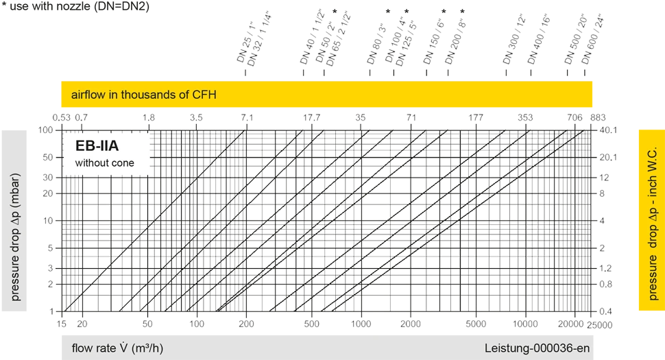
Remark: Flow capacity charts for EB-DN/DN2-IIA/IIB with cone upon request
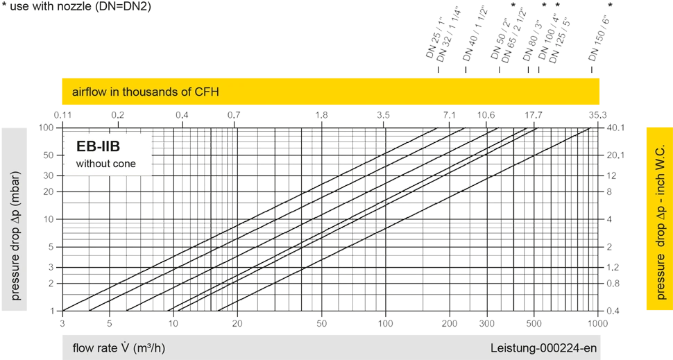
The flow capacity charts have been determined with a calibrated and TÜV certified flow capacity test rig. Volume flow V in (m³/h) and CFH refer to the standard reference conditions of air ISO 6358 (20°C, 1bar). For conversion to other densities and temperatures refer to Sec. 1: “Technical Fundamentals”.


Si vous avez des questions, des commentaires ou des suggestions, notre équipe d'experts se fera un plaisir de vous aider.
